
Location of Jump
Where the balance between upstream and downstream flow depths matches the ratio between y1 and y2.
Note y1 (supercritical) changes more than y2 (subcritical)
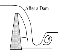
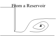
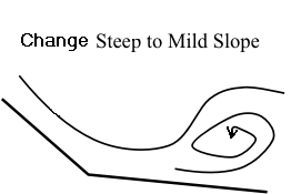
Common Position of Hydraulic Jump
Basic Equations
Cannot use energy equation because of unknown energy loss in jump
Use momentum equation
Fr = γA1z1 - γA2z2 + W sin θ - Fe
ρQ2V2 - ρQ1V1 = γA1z1 - γA2z2 + W sin θ - Fe
For horizontal channel of our flume, sin θ = 0. Also, Fe is the force on the outside of the channel and γ is ρg, so we only use
Q2V2 - Q1V1 = gA1z1 - gA2z2
From this we can get:
Equations Commonly Used
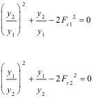
From Prior Equations:
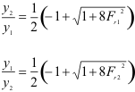
Since y2 is the subcritical flow and more easily measured, we can use the latter form to give the value of y1 that we expect to have. [Note: We must have Fr1 > 1 and Fr2 < 1]
Given y1 and y2 (and the flow rate) we compute the energy loss

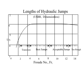
No theory to determine the length of the hydraulic jump, L.
Experimental data plotted into a common graphical form by the US Bureau of Reclamation
An approximate equation in literature gives
L/y1 = 220 tanh((Fr1-1)/22) or
L/y2 = 220 (y1/y2) (tanh(Fr1-1)/22)
Hydraulic Jump Experimental Procedures
Objectives:
Major characteristics of the hydraulic jump.
Y2/Y1 (sequent depth/initial depth) vs. F1 (Froude number @ initial depth)
∆ E/Y1 (energy loss/initial depth) vs. F1,
L/Y2 (length of hydraulic jump/subcritical depth) vs. F1
Water surface profiles of the hydraulic jump by point gage and manometer board readings.
Shape of water surface approaching the drop-off from the rectangular channel
Apparatus:
One-half meter glass-walled flume with sluice gates
Point gage(s) and manometer board with piezometer taps
Procedure:
Set up experiment.
Close the drain valve on the head tank.
Take the zero datum readings for point gages and manometers.
Open the surge tank valve and turn on the large pump.
Conjugate depth and length measurements.
Water surface levels at the initial and sequent depths by point gage readings
Length of the jump within the flow reach (turbulent air bubbles)
Record the flow rate
Check Froude number F1
Repeat at different Froude numbers of about 2-9 by adjusting either the flow rate or the sluice gate opening.
Open the head tank drain valve and shut off the flow.
Hydraulic Jump Experimental Results
Format: Formal.
Data, Calculations, and Results:
Attach your data sheet and a sketch of the experimental set-up.
Plot Y2/Y1 vs. F1 (Froude number at initial depth) for both experimental and theoretical curves.
Plot ∆h/Y1 vs. F1 for both experimental and theoretical curves
Plot L/Y2 (hydraulic jump length/sequent depth) vs. F1.
Plot the water surface profile for the section approaching the drop-off at the end of the channel.
Hydraulic Jump In Flume 
From y0 + v02/2g = y1 + v12/2g and v = Q/by

Merging these two equations gives

If y1 is much less than yo, it can be dropped, or estimated, giving Fr1 as a function of yo & Q
Hydraulic Jump In Our Flume
The channel before the sluice gate is 3 ft high, so yo is 3 ft or less
g is 32.2 ft/S2 and b is 1.64 ft
THUS

(I converted Q from cfs to gpm for our lab)
With the flume full before the sluice gate
| Q (gpm) | Froude # F1 | Depth, y1 | Froude # F1 | ||||||||||||||||||||
|---|---|---|---|---|---|---|---|---|---|---|---|---|---|---|---|---|---|---|---|---|---|---|---|
| (y1 = 3 ft) | (at Q = 600 gpm) | ||||||||||||||||||||||
| 100 | 7.9 | 0.063 | 9.1 | ||||||||||||||||||||
| 150 | 6.9 | 0.067 | 8.4 | ||||||||||||||||||||
| 200 | 6.2 | 0.071 | 7.5 | ||||||||||||||||||||
| 300 | 5.5 | 0.077 | 6.7 | ||||||||||||||||||||
| 400 | 5.0 | 0.089 | 5.5 | ||||||||||||||||||||
| 600 | 4.3 | 0.106 | 4.1 | ||||||||||||||||||||