Weir Photos
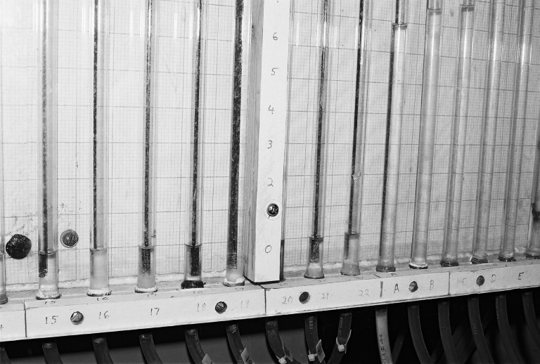
Manometer taps in half-meter flume. A close look shows that this photo is actually during a sluice gate experiment, but the manometer board is the same for both. The order of these manometer taps is 1-22 and then A-F from left to right. Taps 1-22 connect to the flow channel from the bottom, half-way across the channel. Taps A-F for the weir experiment go via a small pipe through the channel bottom just on the downstream side of the weir. See the Weir Taps.jpg for a closer view of the taps on the weir. There is no flow in the channel at this time. The water level is the same in all taps 1-22, and this shows that the bottoms of these tubes are a little below the level of the channel bottom. Note also that the water levels in taps A-F are not at the same level. This is because water has been trapped in those lines.

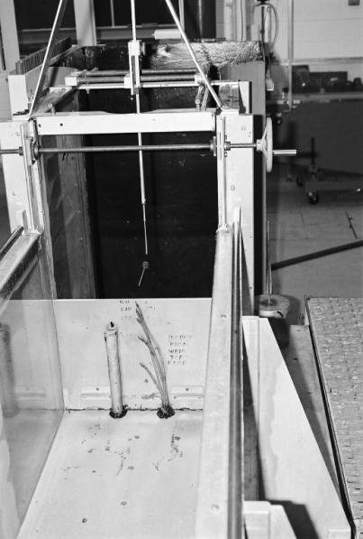
WeirSetupOverview.jpg: Photo of rectangular weir in half-meter flume. You can see the air vent and the lines from the manometer taps coming up through the channel bottom. The locations of the manometer taps can be seen. You also can see part of a point gage just beyond the weir. There is not flow in the channel. (There also are no flow baffles in the channel between the inflow and the weir. I think that is why the vented and unvented flow patterns were not different that day. The entry flow was irregular and air probably was being entrained.) At the right edge, you can see the walk-way beside the channel.
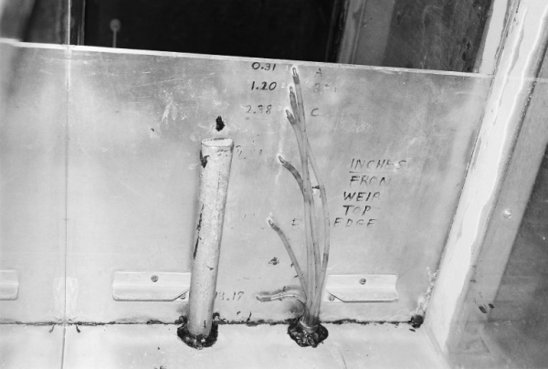
WeirTaps,jpg: Close-up view of the weir from the downstream side. You can see the slight angle on the top edge of the weir, which indicates this is a sharp-crested weir. The sharp side is no the upstream side. You also can see some of the numbers for the distances of the taps from the top of the weir. The “goop” used to seal some edges also shows.
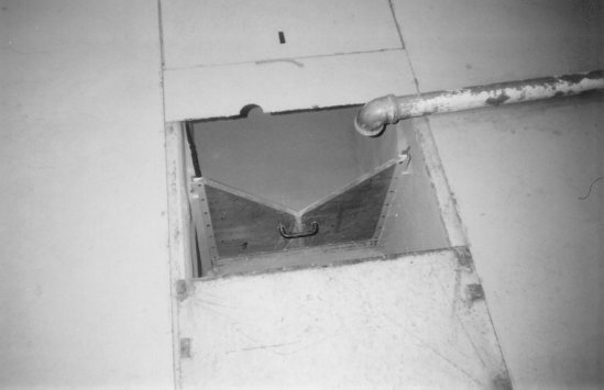
V_NotchWeir.jpg: Photo of v-notch weir, looking down from the floor level just past the v-nptch. There is a small amount of water just overtopping the weir.
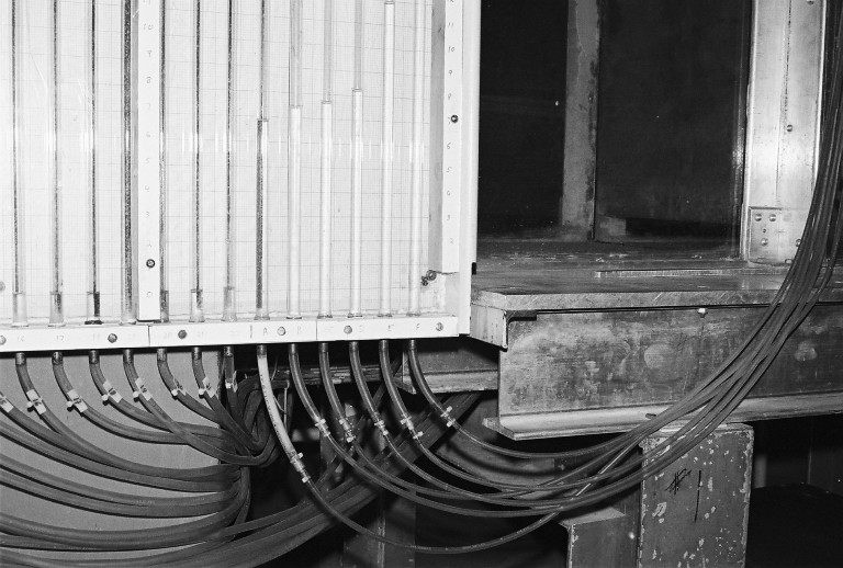
Half-meter flume manometer lines : This is actually a view of the Sluice Gate experiment, but the same manometers are used for the Weir Experiment. The last 6 manometers are taps A-F, on the face of the sluice gate, and are used on the face of the weir for that experiment. In this view, the water levels in taps A through F are clearly higher than the levels on the other taps. For the Weir experiment, this would also be true, although at A-F the levels would all be the same. This is a view with no flow in the flume, shortly after the flow was shut down.
